|
|
| |
|
| |
| .Introduction
And Application |
| AMF
& Engine Control Relay Type –
AMR1 |
|
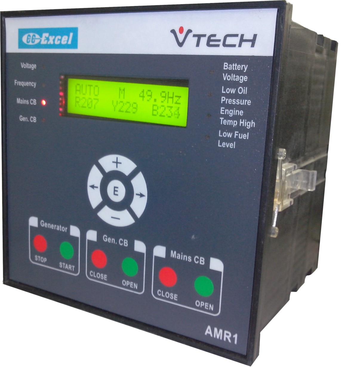
AMR1
has been designed for the control
of emergency and standby power systems.
It integrates the functions of engine
start / stop relay, engine and alternator
supervision and annunciator. The
relay has a user friendly MMI in
the form of a keypad and a LCD display.
The engine start / stop relay element
allows the automatic starting of
relay when power fails, automatic
stopping of the engine when mains
return and also the control and
interlocking of mains and DG Circuit
Breakers. It also includes delayed
supervision of oil pressure switch. |
|
|
|
|
| |
| |
| .Features
& Characteristics |
|
Micro controller
technology |
| |
Wide range of auxiliary supply:
7 V to 35 Vdc |
| |
With stands a dip to 0V of
auxiliary supply for 1 second |
|
Flush mounting |
| |
Alphanumeric LCD display with
keypad for easy of operation |
| |
Display and supervision of
three phase mains voltages for UV, OV & unbalance |
| |
Display and supervision of
D.G voltages for UV, OV |
| |
Display and supervision of
mains & D.G frequency |
| |
Continuous supervision of
mains & D.G breaker status - ensures human
/ equipment safety |
| |
Internal interlock for Mains
& D.G. breaker for fail safe operation |
|
Remote starting and stopping
facilities |
| |
Measuring of different mains
and generator parameters |
| |
True RMS measurement of mains
& D.G. voltage |
| |
Ten internal fault annunciation
for start failure, over speed, low battery, stop
failure etc |
| |
Four spare terminals for connecting
external fault signals |
| |
Display and supervision of
battery voltage |
|
Isolated inputs and outputs |
|
Parameter setting from front
panel keypad |
|
Periodic test feature |
| |
Seven modes: Automatic, Remote,
Manual, Offline, Test , Edit Parameters and Default
Mode |
|
Over speed indication / shutdown |
|
DG starting process supervision |
|
Indication of CB status |
| |
Wide array of time circuits
for start delay, stop delay, mains restoration,
recooling etc |
| |
Serial Communication
(OPTIONAL) |
| |
Ignition
ON input |
|
|
|
| .Functional
Specifications |
Sr.No. |
Parameter |
Specification |
| 1 |
Selection
mode |
Auto |
| 2 |
Manual |
| 3 |
Off |
| 4 |
Remote |
| 5 |
Test |
| 6 |
Functions |
View
actual values
(Default Mode) |
Mains
Voltages |
| 7 |
Mains Frequency |
| 8 |
Generator
Voltage-Phase Voltage |
|
9 |
Generator
Frequency |
| 10 |
Battery Voltage |
| 11 |
View
Set
Parameters
(View Para Mode)* |
Voltage Rated,
Upper and Lower |
| 12 |
Frequency
Rated, Upper and Lower |
| 13 |
Unbalance
Limit for Mains Voltage |
| 14 |
Enable Mains
Operat ion on Single |
| 15 |
Voltage Limit
below which frequency |
| 16 |
Battery voltage
Low value |
| 17 |
Ignition voltage |
| 18 |
Over Speed
Limit |
|
19 |
Number Of
Cranking Attempts |
| 20 |
Generator
Start Delay |
| 21 |
Generator
Cranking Period |
| 22 |
Stopper Delay |
| 23 |
Cranking Wait
Period |
| 24 |
Re-cooling
Time |
| 25 |
Generator
CB on Delay |
| 26 |
Generator
Tripping Delay |
| 27 |
Delayed Supervision |
| 28 |
Generator
Off Delay |
| 29 |
Mains Restoration
Time |
| 30 |
Hooter Reset
Time |
| 31 |
Edit Parameters
(Edit Para Mode)* |
Set all above
parameters. |
|
32 |
View
Values
(Manual/Diagnostic Mode)* |
Engine
Run Hours |
| GCB
Trip Count |
| MCB
Trip Count |
| 33 |
Change Password
(Password Mode)* |
Service password
can be modified. |
| 34 |
Load Default
Mode* |
This mode
loads default parameters,
supervisor password and resets
diagnostics parameter. |
|
35 |
Select
functional mode
(Mode Select Mode)* |
Automatic
mode |
| Remote mode |
| Manual mode |
| Offline mode |
| Test mode |
| 36 |
Supervision |
Three line
voltages of mains
-Voltage band
-Unbalance limit |
| 37 |
One line voltage
of generator
-Voltage band |
| 38 |
Frequency
of mains
-Frequency band |
| 39 |
Frequency
of generator
-Frequency band |
| 40 |
Battery voltage
-Voltage band |
| * This Mode is Protected
by Service Password. |
|
| |
|
| .Performance
Specifications |
| Sr.No. |
Parameter |
Specification |
1 |
Aux Supply |
7.0-35.0 V DC |
2 |
Aux supply Interruption Time |
1 second sustain bat tery dip
down to zero volts for one second without requiring
external capacitor bank. |
3 |
Aux supply Burden |
<3 W @ 24 V DC |
4 |
External cap. Bank |
Not Required |
5 |
Generator Voltage |
50 to 300 V AC (Ph-N) |
6 |
Mains Voltage |
50 to 300 V AC (Ph-N) |
7 |
Rated Frequency |
50 / 60 Hz |
8 |
Voltage Measuring Tolerance |
+/- 1 % |
9 |
Freq. Measuring
Tolerance |
+/- 0.5 % |
10 |
VBatt Supervision |
9.0-35.0 V |
11 |
Tolerance of VBatt Measurement |
+/- 1 % |
|
| |
| |
| .Hardware
Specifications |
| Sr.No. |
Parameter |
Specification |
|
1 |
Display |
16
characters/row x 2 rows LCD display with built in
controller |
| 2 |
Annunciation
using LEDs |
Voltage |
| 3 |
|
Frequency |
| 4 |
|
Mains
CB |
| 5 |
|
Gen
CB |
| 6 |
|
Battery
Voltage |
| 7 |
|
Low
Oil Pressure |
| 8 |
|
Engine
Temp. High |
| 9 |
|
Low
Fuel Level |
| 10 |
Key Pad 11
Keys |
1 |
Edit
Keys
5 Keys |
Forward,
Increment, Decrement,
Backward, Enter |
| |
|
2 |
Control Keys
6 Keys |
Gen
Start, Gen Stop, Open Mains
CB, Close Mains CB, Open DG
CB, Close DG CB |
| 11 |
External faults - 4 |
Opto- isolated I/Ps |
|
12 |
Controls-3 |
Opto-
isolated I/Ps |
Emergency
Stop |
| Remote Stop |
| Remote Start |
| 13 |
Feed Back –
3 |
Opto-
isolated I/Ps |
MCB check back |
| GCB check back |
| Ignition on |
|
14 |
Relay
– 6 nos.
O/P Contact rating
(ALL relays) – 250V
AC, 4A resistive |
N/O
Contacts |
Starter Motor |
| Fuel Injection |
| Decompression Coil (Stopper) |
| Generator CB |
| Hooter |
| Main CB |
15 |
Communication
(OPTIONAL) |
Serial
full duplex RS232 |
16 |
Serial Connector |
9-pin
subminiature D- Connector |
17 |
Storage temp. |
-40°C
- +75°C |
18 |
Operating
temp. |
-20°C
- +70°C |
|
19 |
Connecting
terminals |
2.5
mm Recommended 2.5 mm
conductor
Recommended 2.5 mm
conductor |
20 |
Enclosure |
1.
Flush mounting
2. Bezel : (W x H) 144 x 144 mm , Cut out : 138
x 138
3. Installation Depth: 110 mm (max.)
4. Weight: 0.8 Kg approx. |
|
| |
|
|
|